Debugging SPI
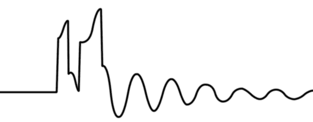
Compare the same SPI command sent from two PICs, one on the breadboard prototype of my Ifos project and one on the PCB-based version:


What gives? There’s a clear sine wave screwing things up, and I’m sure it’s indicative of something basic and obvious… to an electrical engineer (which I’m not). It’s probably somewhere in the first 50 pages of The Art of Electronics, but spoon-fed answers are always welcome, if anyone has a suggestion.
Could it be the SCK and SDO traces are too close together? I don’t think so; I cut the SDO trace back to the μC pin, trying to eliminate all other circuit paths from the equation—same problem. Could it have something to do with the ground plane? Not sure; the breadboard version doesn’t have one, of course. Could it be the ICSP modifications I made, or maybe the MCLR isolation resistor/capacitor/diode I added at the suggestion of some application note? Maybe; it’s worth adding them to the working version to measure their effect. Could it be the power regulation? It seems cleaner for the breadboard version, but the PCB’s is fairly flat, too.
Sometimes I’m just not in the mood to track down mysterious and unexpected problems.
Update (August 7, 2008)
According to my friend Eric Tseo:
“In control system terms, the combination of the signal source and the impedance it drives is an RC circuit that gives you that classic damped ringing.”
He suggests removing components on the signal line and adding them back one at a time. Sounds like a plan.
Update #2 (August 7, 2008)
I went ahead and added the ICSP isolation circuitry to the (working) breadboard version, just to see if it would start misbehaving, too. It continued to work fine…. UNTIL I accidently knocked the ground clip off while positioning the oscilloscope probe. Wonkiness ensued, remarkably similar to the problem waveform above.
Since the ringing problem seemed to affect several signals output by the PIC, I checked its return path to ground. Sure enough, the groundplane is constricted at several points, resulting in a very narrow and circuitous path. A quick test confirmed the cause of the problem: directly connecting the PIC’s Vss to ground (via a wire) resulted in a perfectly clean SPI waveform.
Update #3 (August 10, 2008)
Ok, I feel pretty stupid. After all that, the groundplane doesn’t appear to have been the problem after all. It was my poor choice of ground clip placement. After green-wiring the board to incorporate my experimental fix, the problem remained. Long and short of it: I had clipped to the linear regulator heatsink (because it’s big and easily accessible). That was bad.
So, the actual SPI signals are apparently clean, which means there’s another problem somewhere. I guess problem-solving is fun.
Update #4 (August 19, 2008)
Well, as I freely admit in a later post, there was a lot of tail-chasing here. Impossibly, software was the culprit. I thought that was the part I was supposed to be good at…